 Arboris Botanical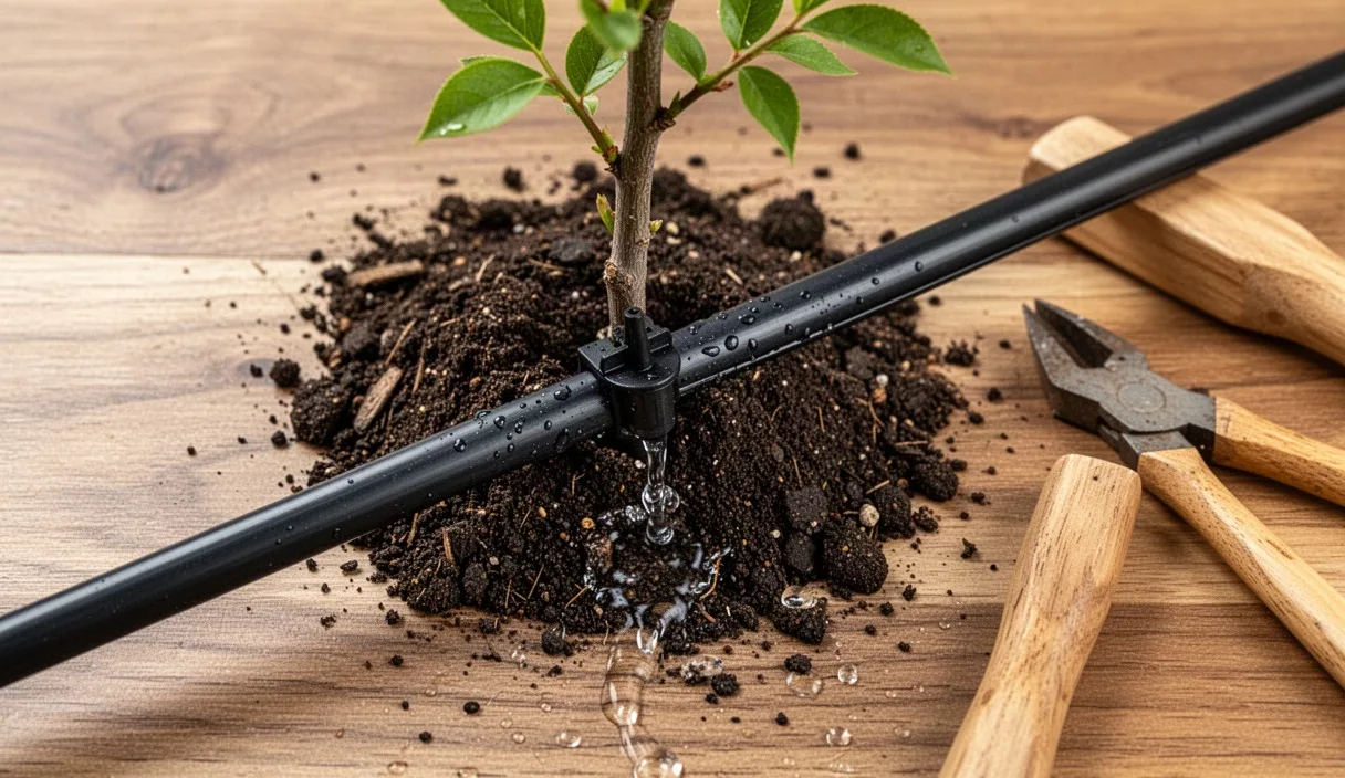
First-year saplings die from underwatering. Bare-root and containerized stock lose up to eighty percent of their active feeder root system during harvest, transit, and planting. Without an established root flare to draw deep subsoil moisture, a young fruit tree depends entirely on the top twelve to eighteen inches of soil. Drip irrigation delivers targeted gallons directly to that re-establishing root mass, cutting water waste from wind drift and evaporation while keeping the surrounding weed seed bank dry.
Establishing orchard trees require precise moisture scheduling to prevent root suffocation or acute vascular wilt. Under-irrigating induces early dormancy, terminal bud set failure, and stunted caliper development. Over-irrigating drives air out of pore spaces, encouraging soil-borne pathogens like Phytophthora cactorum to rot the graft union and crown. Balancing these demands requires calibrated run times, accurate emitter layout, and seasonal volume adjustments matched to your regional reference evapotranspiration.
Transpiration requirements of establishing fruit trees
Saplings drive sap flow through leaf transpiration, pulling water up through xylem tissue via atmospheric demand. Reference evapotranspiration (ETo) dictates this rate. An establishing apple, peach, or pear sapling requires water calculated from regional ETo multiplied by a young-tree crop coefficient (Kc), which starts low in spring and climbs as the leaf canopy expands. For first-year fruit trees, this Kc factor sits between 0.35 during early bud swell and reaches 0.65 to 0.75 by midsummer canopy maturity.
Calculate daily sapling water demand with this standard agronomic formula: Gallons per Day = ETo (inches) x Plant Canopy Area (square feet) x Kc x 0.623 (conversion constant). For a young stone fruit tree with a three-foot diameter canopy (roughly 7.1 square feet of ground cover) on a summer day with an ETo of 0.28 inches, the calculation runs:
0.28 x 7.1 x 0.70 x 0.623 = 0.87 gallons per day.
Young trees do not pull moisture efficiently from the full wetting pattern. System inefficiencies, micro-cracking in the soil, and deep percolation require a distribution uniformity factor. Factoring in an eighty-five percent system efficiency rating, boost that baseline to roughly 1.05 to 1.25 gallons per day during high-heat periods. Peak summer heat waves exceeding ninety-five degrees Fahrenheit with low ambient humidity drive transpiration rates higher, requiring up to 2.5 to 3.5 gallons per tree every forty-eight hours to keep leaves turgid and leaf margins from scorching.
Monitor root-zone tension alongside formulas. Tensiometers or electrical resistance blocks set at eight inches and sixteen inches deep give ground-truth feedback. Target soil moisture tension between 15 and 25 centibars for sandy soils, and between 20 and 40 centibars for medium to heavy loams. Readings creeping past 55 centibars mean the tree is spending metabolic energy fighting soil matrix suction instead of pushing terminal shoot growth.
Line layout: single lateral versus dual lateral drip tubing
Tubing geometry dictates wetting patterns. A single lateral line running down an orchard row works well for the first four to six months after spring planting, provided emitters sit close to the original root plug. As roots expand horizontally beyond the nursery hole, a single run creates an oblong, narrow wetted strip that restricts radial root expansion. Dual lateral lines create a balanced moisture envelope across the row profile, promoting bilateral root anchoring.
| System Attribute | Single Lateral Configuration | Dual Lateral Configuration |
|---|---|---|
| Tubing run per row | One 1/2-inch or 3/4-inch line | Two parallel 1/2-inch lines |
| Emitter placement | In-line or button emitters near trunk | Offset 12 to 18 inches on both sides |
| Wetted root volume | Linear, narrow (14 to 20 inches) | Broad, circular (36 to 48 inches) |
| Material cost | Lower baseline tubing investment | Roughly 70 to 85 percent higher line cost |
| Wind stability support | Moderate; roots track along line | High; roots fan outward evenly |
| Trunk rot risk | Higher if line shifts against bark | Lower; lines stay pinned away from flare |
Single lateral layouts require 1/2-inch (0.600 x 0.700 inch) or 3/4-inch UV-resistant polyethylene tubing. Position two pressure-compensating (PC) button emitters rated at 1.0 gallon per hour (GPH) directly over the root ball: one six inches to the left of the trunk, one six inches to the right. Fasten tubing to an orchard wire suspended twelve to eighteen inches above the ground, or stake it flush to the earth with heavy-duty galvanized wire staples spaced every four feet. Never place an emitter flush against the root crown, because sustained wet bark invites collar rot caused by Phytophthora syringae.
Dual lateral systems split water volume through two parallel tubing runs straddling the tree row, spaced twelve to eighteen inches away from the trunk line on both sides. This geometry doubles the wetted perimeter without waterlogging the center. Run single laterals for low-vigor rootstocks like M.9 apple selections in close spacings, but switch to dual laterals for vigorous semi-dwarf and standard rootstocks such as MM.106, Mazzard cherry, or Lovell peach that require wide, structural root footprints to stay upright in high winds.
Run-time formulas based on sandy loam versus clay loam
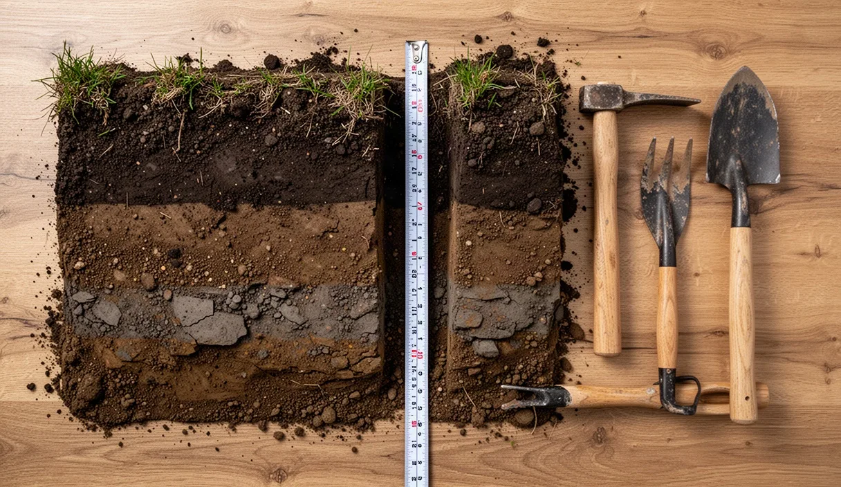
Soil texture governs infiltration rate, water-holding capacity, and lateral capillary drive. Sandy loam soils feature high macro-porosity; water drops straight down with minimal lateral movement, creating an elongated, carrot-shaped wetting bulb. Clay loam soils pull moisture sideways through capillary action, creating an onion-shaped, shallow wetting bulb that spreads broad and flat. Delivering four gallons of water to sandy loam requires a completely different frequency and duration than delivering four gallons to heavy clay.
Determine your system run-time using this calculation: Run Time (hours) = Gallons Needed per Irrigation Event / Total GPH Delivered per Tree. Calculate the delivery based on emitter specs. For a sapling requiring 3.0 gallons per application equipped with two 1.0 GPH emitters (delivering 2.0 GPH total): 3.0 / 2.0 = 1.5 hours (90 minutes).
Sandy loam management
Sandy loams absorb water at rates between 0.8 and 1.5 inches per hour, but hold only 1.1 to 1.4 inches of available water per foot of depth. Water clears the root zone quickly via gravitational drainage. Running drip lines for four straight hours in sand flushes expensive water and mobile nitrate ions below the fourteen-inch root zone, starving the sapling.
- Apply water frequently in brief pulses: three to four times per week.
- Cap run times at 45 to 60 minutes per pulse using 1.0 or 2.0 GPH emitters.
- Space emitters closer together (twelve inches apart) to overlap vertical bulbs.
- Monitor deep leaching using a soil probe twelve hours after irrigation stops.
Clay loam management
Clay loams absorb water slowly, at infiltration rates between 0.1 and 0.3 inches per hour, but store between 1.8 and 2.2 inches of available water per foot of depth. Applying water faster than the soil can accept it causes ponding, lateral runoff, and surface crusting. Subsurface saturation forces oxygen out of microscopic pore spaces, triggering root hypoxia within forty-eight hours.
- Apply water infrequently in slow, deep intervals: one to two times per week.
- Utilize low-output pressure-compensating emitters rated at 0.5 GPH.
- Split single-day applications into cycle-and-soak windows (for example, run 40 minutes on, 50 minutes off, 40 minutes on) to allow lateral absorption.
- Check the soil fifteen inches down; refrain from irrigating if clay rolls into a tight, slick ribbon between your fingers.
Placement: moving emitters outward as root radius widens
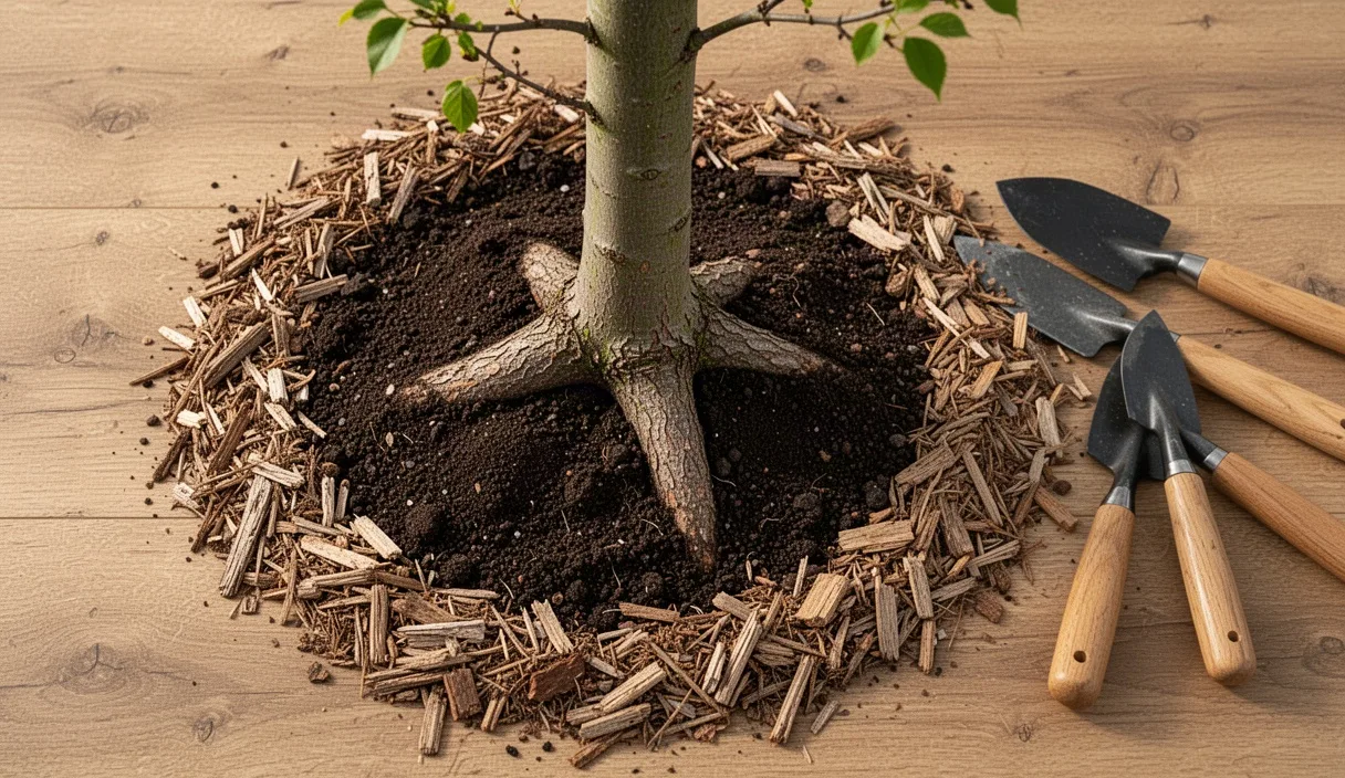
First-year roots do not stay confined inside the nursery hole. Under proper moisture conditions, horizontal lateral root extensions grow eighteen to thirty inches beyond the original planting pocket by late August. Leaving drip emitters pinned directly over the crown during this rapid expansion creates two major problems: it chokes root development into a tight, root-bound ball, and it leaves newly generated peripheral root tips parched in dry inter-row soil.
Adjust emitter points three times over the course of the initial growing season to guide outward structural growth.
Setting the planting baseline (spring bud break to week six)
Keep emitters parked directly over the nursery root profile. For bare-root trees, pin two 1.0 GPH emitters six inches out from the trunk. For container stock, orient emitters directly above the boundary where container potting mix meets native backfill. This interface forms a hydraulic barrier; potting mixes high in peat or pine bark shed water easily if allowed to dry, while surrounding native soil pulls water away from the root ball if emitters are installed too far outward.
Executing the mid-season shift (weeks seven to fourteen)
By late June, root tips penetrate native soil outside the planting hole. Punch two additional emitters into the lateral lines, or unseat your existing button emitters and move them outward. Locate emitters twelve to fifteen inches away from the trunk. Cap off the internal emitter holes using 1/4-inch gooseneck plugs if your layout does not permit adding more volume. The central trunk area no longer requires direct point-source wetting. Soil capillary action will supply sufficient ambient moisture back toward the center while the expanding wetting front draws feeder roots outward.
Finalizing late summer placement (week fifteen to leaf drop)
By mid-August, establishing root systems occupy a thirty-six to forty-inch circle around the trunk base. Shift emitters out to eighteen to twenty-four inches from the tree trunk. If using dual laterals, verify that tubing lines sit eighteen inches off the tree row centerline on both sides. This creates a uniform moisture grid across the alley margins. Stop moving emitters outward sixty days before your average first fall freeze date to allow wood to mature and prevent late-season soft vegetative flushes that suffer winterkill.
Winterization blowout protocols to protect drip manifolds
Trapped water bursts polyethylene lines, cracks plastic filter bowls, and destroys brass solenoid internal chambers when winter freezes arrive. Relying solely on gravity drain valves leaves water trapped in line dips, low spots, and tortuous emitter flow paths. A complete system blowout using clean compressed air guarantees clear plumbing, safeguarding your capital investment for the spring push.
Do not connect high-pressure shop compressors directly to drip lines without regulated controls. Polyethylene tubing bursts at forty to fifty psi when subjected to sudden, unbuffered air volume surges. Follow these structured operational steps:
Isolate the main water supply and relieve residual head
Shut off the main backflow prevention assembly isolation valve. Open the manual system drain valve at the lowest physical elevation point in the mainline. Open all manual field valves, zone manifolds, and flush caps on lateral run ends to bleed out gravitational water.
Install the pneumatic connection assembly
Thread an air blowout fitting equipped with an industrial quick-connect plug into the winterization port located immediately downstream of the backflow preventer. Never inject compressed air through a backflow preventer; the heat and pressure deform rubber check valves, damage internal relief valves, and ruin plastic poppets. Secure a clean air compressor equipped with an accurate inline pressure regulator.
Adjust compressor settings and purge lines
Set the compressor regulator to an absolute ceiling of 30 to 35 psi for thin-wall drip tape or 40 to 45 psi for heavy-duty blank poly line. Drip lines require air volume (CFM) rather than high pressure (PSI) to carry water out through emitters and open flush valves. A small pancake compressor will overheat; utilize a compressor delivering at least 8 to 12 CFM. Open zone valves one at a time. Run air through the line until a fine mist gives way to a dry aerosol hiss at the open terminal flush valves, which typically takes two to three minutes per lateral run.
Winterize downstream manifold components
Remove the bowl and clean the stainless steel or plastic disc filter screen. Reassemble the housing dry, or leave the filter element in a shop container over winter. Unscrew the solenoid and manual bleed pins on all automatic irrigation valves one full turn to allow water caught inside the valve bonnet chamber to escape. Leave end-line flush caps open or loosely threaded through winter to prevent interior condensation buildup and allow freeze expansion relief.
Common mistakes
- Flooding the root collar: Directing emitter output straight at the tree trunk keeps bark wet, inviting crown rot and wood-boring insects. Keep water at least six inches away from the bark.
- Irrigating by calendar rather than conditions: Running identical forty-minute programs during rainy weeks saturates the root envelope and triggers fungal root dieback. Alter run times based on real temperature, cloud cover, and soil feel.
- Omitting a pressure regulator: Drip systems operate best between 15 and 30 psi. Hooking poly line directly to an unmitigated 65 psi domestic well blows emitters out of their punched barbs, cutting delivery to zero.
- Ignoring water filtration: Silt, rust flakes, and algae clog microscopic emitter labyrinths fast. Always install a 120 to 155-mesh screen or disc filter directly upstream of your drip lines.
- Burying standard drip lines under deep soil: Covering poly tubing with topsoil prevents visual emitter inspection and allows root intrusion into the barbs. Secure lines on top of native soil and cover them with two to three inches of wood chip mulch instead.
Practical next steps for setup
Grab a soil sample from the planned planting row and conduct a quick ribbon test. Confirm whether your native ground leans toward loose sand, balanced loam, or heavy clay to establish base run times and pick your emitter flow rates. Source high-quality 0.5 GPH, 1.0 GPH, or 2.0 GPH pressure-compensating button emitters, UV-resistant 1/2-inch poly supply tubing, a 25-psi preset pressure regulator, and a 150-mesh screen filter.
Lay out your mainline and secure lateral tubing before saplings arrive for planting. Test-fire the system under line pressure to verify that every emitter drips properly, check connections for pinhole leaks, and calculate the true delivered flow rate into a catch cup over a fifteen-minute test window. For extensive multi-acre commercial installations, complex grading challenges, or municipal water tie-ins requiring certified backflow testing, consult an experienced irrigation engineer or licensed landscape contractor.